Mavic unveils Cosmic CXR60
Mavic unveiled the latest additions to the CXR WTS (Wheel-Tire System) wheel lineup that it first introduced a year ago beginning with the Cosmic CXR80 tubular wheel set. As we learned at the time, this is a renewed effort by Mavic to look at their wheel designs as a total system and how each of the components contribute to the overall performance. This includes not only the easily tangible qualities, such as weight and stiffness, but in the less tangible, yet in many ways more important factors such as aerodynamics.
This was a welcome change from a company which had introduced the venerable Mavic Cosmic Carbone many years prior but had seemed to concentrate in recent years on stiffness and mass over all other performance properties of their wheel offerings.
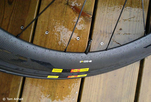
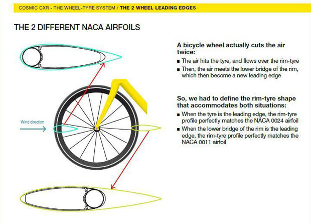
In their development of the CXR wheel lineup, Mavic has taken an approach that attempts to minimize the air flow separation at both the tire-leading and rim-leading sections of the wheel. In both cases, they've looked to follow a classic NACA defined symmetric air foil shape as much as possible, with the tire-leading side following the particular NACA shape more completely, and the rim-leading section following a different, and narrower, NACA shape, but with the tail effectively being "truncated" by the presence of the tire section. In a way, this approach is basically the opposite of what has recently been put forth recently by competitors such as Zipp, Bontrager, and Hed, where their emphasis is on optimization of the rim-leading portion (i.e. the trailing half) of the wheel cross-section. But, as we'll see later, this isn't the only part of the wheel line design where Mavic is bucking the latest wheel trends.
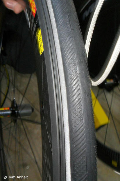
With their emphasis on the tire-leading portion of the system, it was imperative that Mavic was able to design and implement under their own control a tire which would present the proper parabolic profile on the leading edge of the wheel. This has resulted in the development of their CXR Yksion tubular tires (GripLink front and PowerLink rear) last year, and with the introduction of the CXR60 clincher version, the new CXR Yksion clincher tires. Being made from a flexible material and inflated with air pressure, it's difficult to control the precise external shape of a tire. You can get close, but in the end there are always variances. So, Mavic relies on an old trick of the aerodynamics trade. On the sidewalls of the tire is molded a specific pattern which to the uninitiated may look like traction grooves. In fact, Mavic sponsored triathlete Frederik Van Lierde commented that when he was first sent the CXR tires last year, he thought that they were rain tires due to the patterning. He didn't realize that the pattern is actually an aerodynamic device known as a "boundary layer trip."
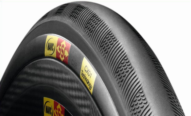
The way that this pattern works is that the flow of air around an object has momentum and doesn't change direction easily. This is why aerodynamic shapes have very slowly changing curvatures. If the shape changes too fast, then flow separation occurs since the momentum of the air tends to cause it to keep flowing in the same direction. The idea is to keep the air moving as smoothly as possible so that the flow doesn't separate from the surface and start forming turbulent eddies. As soon as that happens, the drag of the object increases dramatically. This is sometimes referred to as stall. However, it was found that in some cases it can be helpful to have small disturbances further up in the flow field around the object that act as a trip and form a very small turbulent air layer right on the surface of the object. Although this trip actually adds a small amount of drag, this small layer of turbulent fluid, in a sense, slightly changes the effective shape of the object so that the smooth air flow travels over it. This can delay the large separation of flow so that it occurs further back on the object, thereby reducing the drag of the object over a wider range of yaw angles than if it the feature wasn't there in the first place. The direct effect of the patterning can be seen in the drag plots for the CXR wheels, where the stall angle of the wheels are at higher values than other wheels with other tires.
An additional part of the Wheel-Tire System is the CX01 blades which are used to "fill the gap" which is normally present at the junction of a tire and rim. As discussed above, any dramatic shape changes in the air flow field can cause flow separation and thus increase the drag of the object. The valley typically formed by the tire to wheel junction, whether it be a clincher or tubular design, presents one such of an area. The idea of the CX01 blades is to fill that valley in and thus add an additional drag reduction. As we saw last year, these blades are made from a flexible rubber flap which is bonded to a rigid plastic mount and the resulting structure clips into a mating groove on the rims. At the present time, the CX01 blades aren't allowed for use in UCI regulated competitions (Mavic is still in discussions about getting them approved for use with the UCI) but for the majority of the Mavic buying public (i.e. most triathletes world-wide and road riders in the US) that should not be an issue since their equipment isn't required to comply with the UCI regulations.
Lastly, the hubs for the CXR wheel line are all the same as the hubs that were introduced last year on the CXR 80 and have been specifically designed to be what they consider the best compromise between aerodynamics, flange height and spacing (and the resulting wheel stiffness), and mass. The thin, bladed steel spokes used on all wheels in the CXR line are identical except for the specific length required for the individual models.
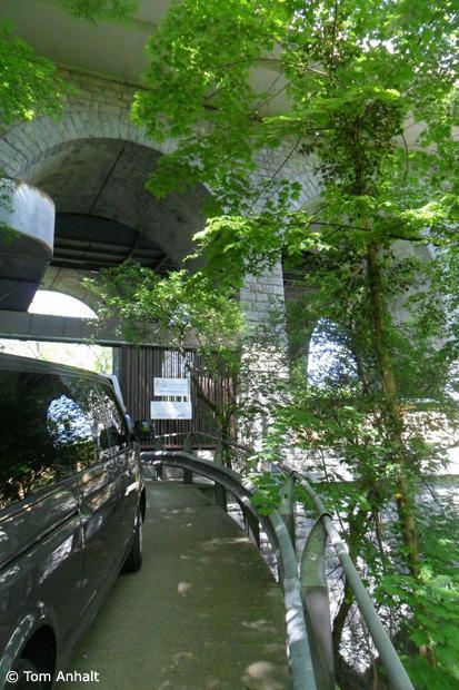
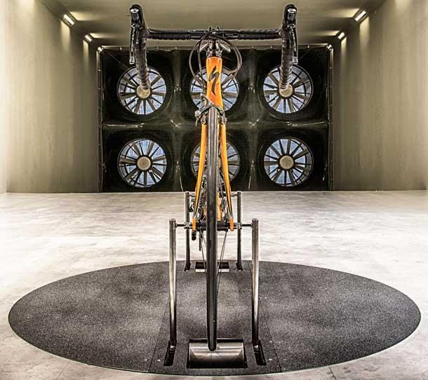
To introduce the newest members of their CXR wheel line, Mavic invited a group of journalists to the wind tunnel located at the CFME, an acronym that in English represents the Competence Group in Fluid Mechanics and Energetics in Geneva, which is a part of HEPIA, or the University of Architecture, Engineering, and Landscaping in Geneva. This unique facility is located just a ½ hour drive from Mavic's Annecy headquarters just over the border in France, which means that its location allows for easy access by the Mavic engineers. The history of the wind tunnel in this location is very interesting in that it is actually built within the walls of what was intended to originally be a train tunnel cut into the side of a hill in the 1920s. The train access was never realized, and when the building that was housing the university's original aero lab was slated to be torn down in the mid-80s, the director at the time realized that the current site could be re-purposed to create a unique structure. One of the main advantages of having the reinforced concrete walls of the tunnel basically imbedded in the side of a hill is that the ambient temperature and humidity ends up being fairly constant year-round. Think of it as a high-tech wine cellar. The current facility was completed in 1995.
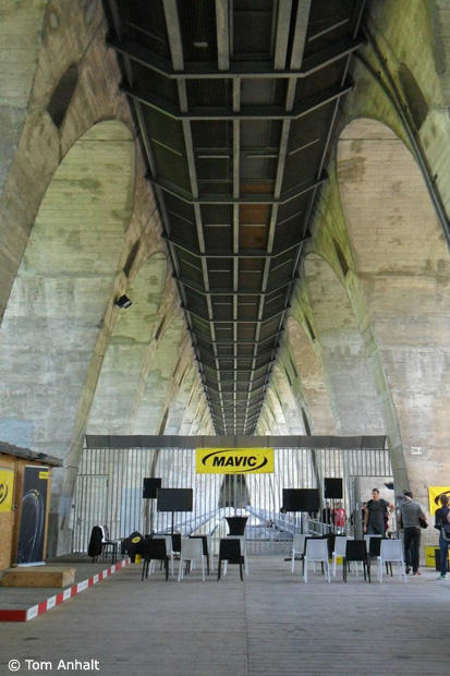
The wind tunnel design is what is known as a closed-circuit layout, in that the air flow is drawn through the central test section and then recirculated around the outside of that structure between it and the tunnel walls. This is in contrast to open circuit designs such as the A2 and the newly announced Specialized wind tunnel. Traditionally, the closed-circuit design is considered to be preferred format due to having better control of the air during the testing. There are caps at either end of the tunnel that split and guide the air flow in making the necessary 180 degree turns. In a discussion with the Director of the Facility, Dr. Flavio Noca, I asked him if because of the tapered cathedral shape of the tunnel walls there were any special tricks or features used to prevent uneven flow through the circuit. He explained that the entire setup was tested as a scale model in the university's hydrodynamics lab so that they could better visualize the flow and minimize any issues.

He further explained that even though water obviously isn't the same as air, as long as the Reynolds number, a value that characterizes the flow properties based on fluid density, viscosity, and velocity relative to the size of the object being tested of the test setup was identical to the full scale facility in air, the results are interchangeable. He even hinted that the use of hydrodynamic testing on future Mavic designs may be employed specifically because of that better flow visualization while testing.
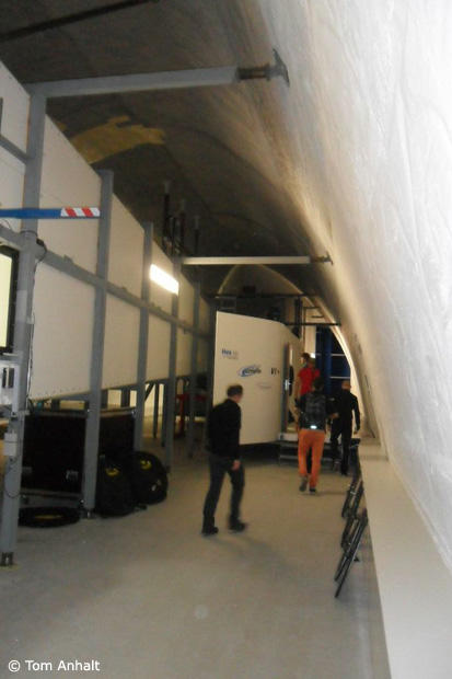
Obviously, the CFME wind tunnel wasn't specifically designed for testing bicycles and components, but for the size of the test section (2m wide x 1.5m tall) it should be more than adequate for testing wheels and complete bikes at low yaw angles. However, by my calculations it may not be quite large enough for the best results for complete bikes at high yaw angles. And for a bike with a rider on board, even at zero yaw angle the blockage of the tunnel is well above the 5% rule of thumb typically used as a gauge for getting accurate results. But that doesn't necessarily mean that comparative testing wouldn't be useful for those configurations, it's just that the absolute values may not be accurate. There are ways to mathematically compensate for this blockage, but the use of them adds more uncertainty to the measurement accuracy.
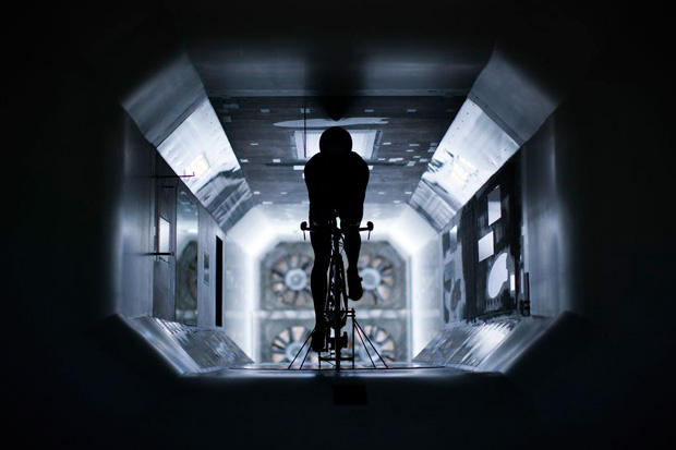
For wheel and bike testing, Mavic designed and constructed their own force balance mechanism. They did this because they wanted a setup which wouldn't be a compromise of an existing balance which was designed for more general usage. For example, they wanted to make sure that the balance rotated with the object under test so that the forces being read out were always in the reference frame of the bike (i.e. aligned to the fore-aft axis of the bike) so that the most accurate results could be obtained. If the force sensors don't rotate with the bike and instead stay aligned with the flow direction, then that means that some of the measurement accuracy is lost during the trigonometric conversions necessary to get the values into the bike frame of reference. As part of the design, the front fork mounts are also spread relatively wide so that interactions between the mounts and the bike are lessened when they are tested at non-zero yaw angles.
One thing that the Mavic engineers wanted to make sure they were able to capture was not only the translation drag force on the items they were testing, but also the power required to rotate the wheels while being exposed to the translation air flow, or the “power to rotate”. To do so, they came up with a design where instead of the wheels being driven by a solid roller during testing, the tires instead lightly contact a belt below each wheel. Since the tire contacts the belt on an unsupported span between two pulleys and the object under test is supported by the balance mounting fixture, that means that there is only an extremely small amount of deflection in the tire, which helps to minimize the effects of tire rolling resistance on the power required rotate the wheels. There is just enough contact between the belt and the tire to prevent slipping, and the speed of each wheel is matched to the air speed of the test section. For rider testing under power, Mavic is in the process of developing a Comete disc that will have an electronic brake built into it so that the rider can pedal against a realistic load. The Mavic engineers claim that the balance will measure to a precision of +/- 2.5g for a wheel, and +/-5-10g for a pedaling cyclist.
Well…enough about the design and facilities, let's talk about the wheels. The new CXR60 wheel range is composed of a tubular (CXR60T) and a clincher version (CXR60C), both with a depth of 60mm. The tubular version is based on the NACA 0029 and 0017 foil profiles, while the clincher version, apparently due to design restrictions related to the clincher construction, is based on the NACA 0027 and 0012 profiles.
Here's a quick primer on NACA foil designations: the first 2 digits of the 4 digit number represent the curvature of the centerline of the air foil. In this case we're talking about air foils that are symmetric, and thus have a straight center line, so those numbers end up being zero. The final 2 numbers represent the ratio of the maximum width as compared to the overall length of the foil, as a percentage. For example, the 0029 designation mentioned above means that the cross section width is 29% of the overall length. For a wheel, this overall length means the total length of the rim including the tire. A 60mm depth rim, plus a 23mm tall tire results in a total length of 93mm. 29% of 93mm is 27mm, or what is claimed as the maximum width for the CXR60T. The CXR60C uses a 0027 designated section, so it has a slightly narrower overall width.
The tire used on the CXR60T is the same tubular tire as was introduced with the CXR80 wheel last year. Although technically the profiles of the leading edges of both wheel designs are slightly different, they're close enough that using the tire designed for the 80mm deep wheel doesn't appreciably affect the performance. Surely, the boundary layer trip features on the tire sidewalls help to minimize that as an issue.
For the clincher version, the tires are a brand new product and although appear outwardly the same as their tubular counterparts, they are in fact nearly completely different aside from the sidewall patterning. The clincher tires are supplied by a different source than the tubulars, and the casings and compounds are different as well. Mavic is fairly quiet on the details of the tire construction, but I was able to get out of them that the clincher version is based on a 127tpi nylon casing. They were silent on whether the compound was carbon or silica filled, though. Apparently, the rolling resistance of the clincher tires is approximately 3-4W lower than the tubular, but that figure is for a smooth surface and with butyl tubes, which means that for a typical road surface roughness, the difference would actually be more on the range of 5-6W. Replace the butyl tube with a latex one, and the Crr difference would be even greater, and based on measurements I've made of the tubular tire, perhaps as much as twice that amount. I'm anxious to get my hands on the clincher tires to do some roller testing to confirm these figures.
The basic structure of the CXR60T tubular setup is nearly identical to the CXR80 design, so I'll instead concentrate on the new features of the CXR60C clincher model. When I first got a look at the new clincher model, my first thought was that it's basically an updated Cosmic Carbone SLE with its aluminum rim with carbon cap construction. It has the same Exalith braking track, and unlike the tubular CXR wheels, even the weave of the carbon cap is the same as the older Carbone. The big difference though, aside from the deeper section of the cap as compared to the older wheel, is the fact that the aluminum rim has been completely reconfigured. The width between the braking surfaces has been increased, but that wasn't enough to make room for the CX01 blades. That means that Mavic needed to take the approach of actually decreasing the internal width between the bead hooks from a typical 15mm (on a 19mm external width rim) to 13mm. That's what I was talking about when I said that some of design decisions are bucking the current industry trends, where most wheel makers are currently increasing that dimension. Although many wheel manufacturers are selling that increased width as an advantage in handling or rolling resistance, in reality there is little, if any, evidence to back up those claims. In fact, as Slowtwitch's Greg Kopecky has pointed out, many folks are putting tires on clincher rims that are narrower than what is advised by the ISO standards for those particular rim widths. The only real advantage of running narrower tires than the standard allows on wider rims is better matching of the tire width to the rim width for better aerodynamics. Knowing this, the engineers at Mavic decided that it was overall better to reduce that internal bead seat dimension to allow the inclusion of the CX01 blades instead. The actual performance would be better overall and the tire retention would be improved as a bonus.
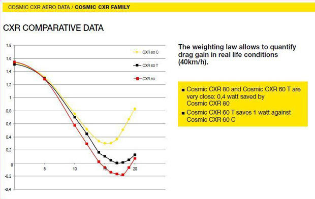
OK. Time for the data. Mavic provided the drag charts for both wheels in comparison to competitor designs and also in relation to each other. Those you can see below. As expected, their data shows the new wheels to do very well aerodynamically as compared to the selected competitor setups, with the performance at higher yaws being the largest differentiator. It's also interesting to note that unlike some other setups we've seen, the behavior of the Mavic wheel drag curves at yaw angles above their stall points is much smoother and results in a less dramatic increase in drag above yaw. This shows that the Mavic engineers have done their homework on the drag performance.
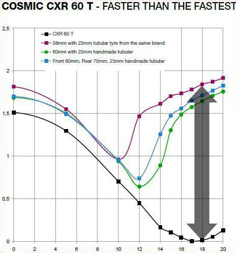
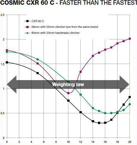
They also did live testing during the event, where they compared their 2 new wheels against a Bontrager D3 Aeolus 5 clincher with a Bontrager R4 Aero tire, and an Enve 6.7 front wheel with a Vittoria Corsa CX tire. That data was similar to what is shown above and basically confirmed their prior measurements.
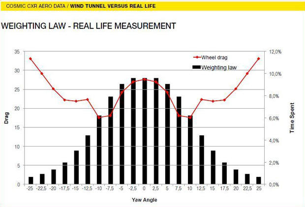
Additionally, as with the CXR80 introduction, they also discussed the data they took with their own wind angle device during outside riding and the resulting average percent time at yaw angle plot. They used this data to create a weighted averaging approach for the wheel data to more realistically compare power differences between wheel designs. The weighted average actually values low yaw angle performance to a greater degree, but the Mavic wheel designs tend to perform much better than their competition at higher yaw angles, where they don't stall as early, nor as dramatically. Even so, according to the weighted average, the Mavic wheels still come out ahead aerodynamically. Additionally, because the data used to form the weighted average was from a large number of rides and riders, that means that it's possible that the same plot for a slower than average rider might be flatter and thus more highly value the higher yaw angles. That would again favor the Mavic wheels.
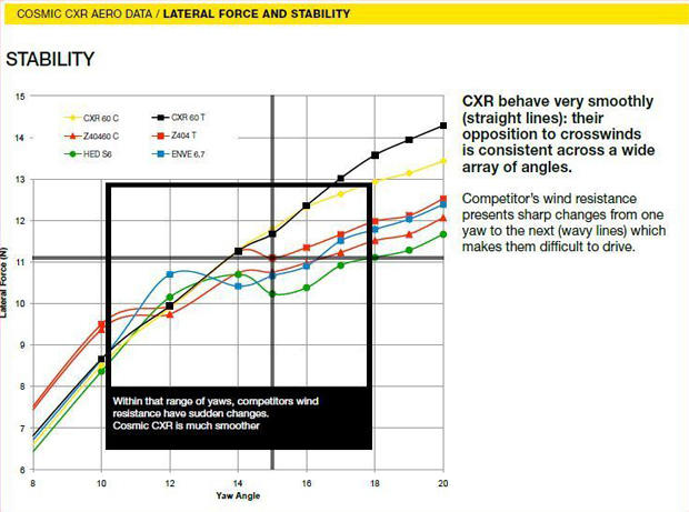
Another set of data that they presented was the total side force on the wheels. This is the force acting perpendicular to the direction of travel. In general, the deeper the wheel, the more side force that is generated in a cross wind due to the increased surface area. In those plots, the curves for the Mavic wheels demonstrate a nearly constant slope with respect to yaw angle, meaning that the side force changes in a smooth and linear fashion. They pointed out that the side force of some competitor wheels appears to vary around at the higher yaws, asserting that this would result in more unpredictable handling. That would be true if side force was the only thing affecting handling in this regard, but in reality it's the fact that a center of pressure of the force on a front wheel is usually close to the center of the wheel, but the steering axis is offset from the center. This means that this offset results in a steering torque about that axis. However, we know that some wheels are designed to move that center of pressure point rearward to be more closely aligned with the steering axis and thereby lessening the steering torque no matter the magnitude of the actual side force. Based on that, it's not clear how well the design of the CXR60 wheels has addressed the steering torque issue. If the center of pressure is still offset from the steering axis, then it's entirely possible that these designs would end up with more steering torque input as compared to other designs.
On the power to rotate figures, there weren't any separate plots of those values, and it was unclear if those measurements are included in the drag charts above or not. For the 2 test runs I observed, the force to rotate values appeared to be fairly flat over the +/-20 deg test yaw range, with the CXR60C taking ~-0.35N at the contact patch and the Bontrager wheel taking ~0.1N more at ~0.45N. It's important to remember that this force measurement includes the resistance of the wheel bearings. Mavic claimed that the typical power to rotate measurements they've taken are usually between 15-30% of the translational drag. Based on the drag values seen during the wheel testing, the values observed above match that assertion. I asked about what sorts of measurements they see on wheels with solid spokes, such as the H3 or their own iO track wheel, and I was told that they had actually designed a new iO wheel that dramatically drops the power to rotate requirements.
Now, on to one of the performance factors of lesser importance: the mass. Both of the CXR60 wheels are not what most would consider light weight, but that really shouldn't be an issue. At claimed masses of 1645g and 1825g for the tubular and clincher versions of the wheel sets respectively, the wheels are not largely out of line with wheels of similar construction and performance. Despite popular opinions to the contrary, the physics of the cycling show that even when including rotational inertia, wheel mass effects (within the range of reasonable variances) are basically an order of magnitude less important than other properties such as aerodynamics, even for fairly steep climbing. Enough said.
Overall, these 2 new wheel systems from Mavic emphasize their renewed efforts at addressing the aerodynamics of their wheels and using a systems approach to their wheel designs. For this, they should be applauded. In taking that systems level approach though, it would be valuable if they were to include the effects of the rolling resistance properties of their tires, especially since the optimum aero properties of their products depends on the tires. In their presentation, they showed that using their weighted average of yaw angles, the clincher version is within 0.4W of the tubular version in aero drag power. In the testing that was observed during the presentations, the clincher version was actually slightly lower drag than the tubular between 0 and 10-12 degrees of yaw. Considering that the rolling resistance of the clincher tires results in a 10X greater difference at least (and most likely MUCH higher on “real roads” and with latex tubes) it's pretty clear to see that the clincher version of the CXR60 is the big standout in the lineup here and is the better performer of the two, and is arguably an even better performance choice than the CXR80. With its Exalith brake tracks, it has the potential to be the do all wheel set of choice. A rider could just remove the CX01 blades, put on some wider and more durable tires, and use them for training. Training on deep wheels is an important factor in becoming comfortable with them for racing. Then when race day comes, they could easily swap the rubber for the Yksion CXR clincher tires and install the CX01 blades and go race. It wouldn't even require a brake pad swap, and the braking would always be excellent.
Shown below is a plot of the CXR60 wheel performance if the rolling resistance is included. To create that plot, I used Mavic's own weighting law and aero drag data and combined it with rolling resistance measurements, see blog post here for more detail: http://bikeblather.blogspot.com/2013/04/why-tire-crr-matters.html. For the new CXR Yksion tires, I used an assumed Crr value based on the measurements of the tubular version, with the differences noted by Mavic subtracted out (real world values, not smooth surface). As you can see, the CXR80 and CXR60T have nearly identical performance, mostly due to the use of the same tires, but also due in part to the very close aerodynamic performance, with the CXR80 pulling slightly ahead at higher expected apparent wind velocities. The interesting thing is that even with just the Crr difference quoted by Mavic for the new clincher tires (adjusted by a factor of 1.5x to represent the performance on real world road roughness) the CXR60C handily beats the other wheels in the CXR line over the entire range of apparent wind speeds shown. Also included in that plot is a curve showing the expected overall aero+rolling resistance performance of the Bontrager D3 Aeolus 5 clincher wheel with Bontrager's R4 Aero tire. For the rolling resistance of the R4 Aero, I used the value I measured in roller testing with a latex tube installed. Despite the Mavic wheels' better aero performance, the lower rolling resistance of the Bontrager setup allows it to handily beat the Mavic wheels, and it only begins to be beaten by the CXR60C at apparent wind speeds greater than 55 kph, which is a VERY high wind speed. Of course, it's also possible that putting a latex tube inside the Yksion tires could drop their Crr to be close to that of the R4 Aero, at which time the advantage would go to the CXR60C due to it's better aero performance, as represented by the shallower slope of its combined aero+Crr drag curve. This potential outstanding performance for the CXR60C also points to the fact that a clincher version of the CXR80 would also be a stellar performer. When asked about if that was in the plans, the Mavic folks were a bit coy on the subject and said that they want to concentrate on the CXR60s this year, but that a CXR80C might be an option in the future.
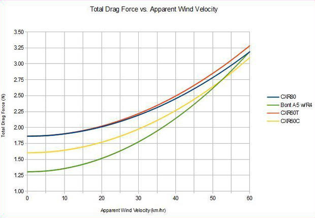
Looking at the above, it's fairly obvious that the most exciting wheel of the Mavic CXR lineup is actually the clincher CXR60C. It delivers world class aerodynamics and will possibly have a low enough rolling resistance so that it remains competitive against similar wheels, and perhaps even better performing than other wheels of deeper rim dimensions…including it's own stable-mate, the CXR80. Couple that with the ability to easily run other tires for training purposes, along with the excellent aluminum based Exalith braking track, and it's not hard to see why it's the overachiever of the bunch.
The stated availability of the wheels was July for the CXR60T and September for the CXR60C. As of this writing, the US pricing was unavailable, but I would expect it to be similar to the CXR80 ($2799, including tires, CX01 blades, brake pads, valve extenders, and wheel bags) for the CXR60T tubular version, with a slightly lower pricing for the CXR60C clinchers.


Start the discussion at slowtwitch.northend.network